Information Strategy and Technology Services (ISTS) have established high class data centres at the Mawson Lakes and City West campuses and encourage Departments and Units within the University to consider hosting their equipment in one or both of these data centres.
Each data centre provides redundant power, air-conditioning and network connectivity along with a sophisticated fire detection and suppression system. The data centres are connected via a redundant, high speed network.
The following sections serve to provide details around the service being offered.
In order to ensure efficient and effective management and allocation of the finite data centre resources, requests for equipment hosting must outline the reasons why the equipment is required to be hosted in the data centre and be approved by ISTS.
Scope of Data Centre Services are outlined in sections 3.1 - 3.6 below.
Power connections (plugs) must be compatible with our existing infrastructure and Australian standards.
The Data Centre’s standard is:
Other options can be accommodated, but consultation with Network Services will be required in advance and additional costs may be passed on to the client.
Higher powered equipment may require a direct under floor connection; this will require an Australian standard plug type, or the retro fitting of one prior to installation, the connection options is as follows:
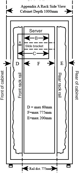
When ordering equipment, please take into consideration Data Centre rack dimensions. If they do not comply please consult with Network Services. See standard rack information below:
Some equipment may not be compatible with the data centres standard racking; for example, a self-contained storage array, oversized rack mounted equipment or some other specialised device.
Floor space is at a premium in both Data Centre’s, so discussion with Network Services will be required well in advance to determine if floor space is available and arrange connectivity to existing services.
ISTS Data Centres have high levels of fibre connectivity, but in some cases the existing infrastructure may not have sufficient capacity or be suitable. Fibre requirements should be discussed well in advance with Network Services and if additional installation is required, this may be subject to cost recovery.
ISTS Data Centres have in rack switching with provision for two or more network connections per server. Network connectivity is supplied by Network Services, but the client will need to communicate their requirements well in advance, so that the required services are in place prior to installation.
The process for requesting hosting services is as follows:
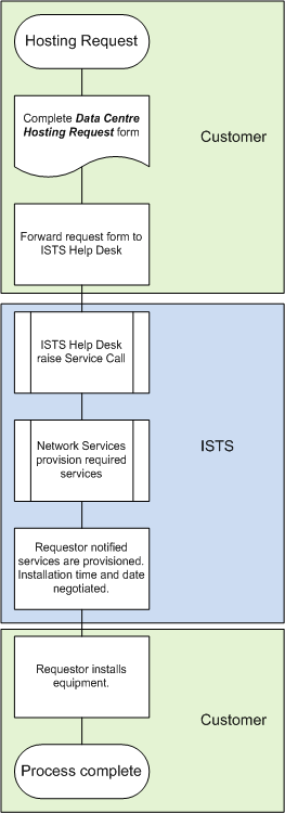
More specific details can be found in sections 4.1 - 4.5 below.
The lead times for provisioning of services can vary due to the need to engage external contractors for some work. Lead time targets are as follows:
ISTS will endeavour to always provision services as quickly as possible, however, the above lead times should be considered the minimum expected times to provision a service.
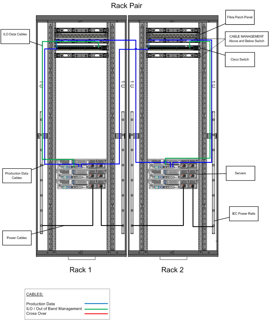
All equipment installed in the data centre must be patched using the ISTS cabling conventions.
Please consult with Network Services to verify power requirements and available options.
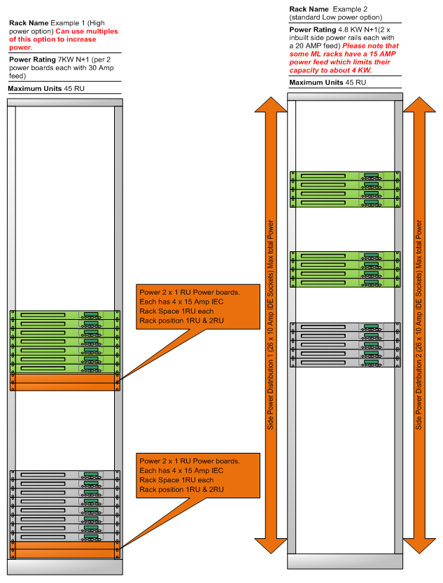
Data Centre rack configuration:
In order to provide the best level of availability, ensure capacity requirements are balanced and hosted equipment poses no safety risk, the following minimum equipment standards must be met by the customer:
If there is a need to host equipment that does not meet the above standards then this need will be reviewed by Network Services on a case by case basis.
In order to provide a trouble free and safe environment ISTS reserves the right to:
The customer shall submit requests via the ISTS Help desk for all removal and installation of equipment.
All customers and third party providers requiring access to the data centres must have completed an induction, signed the “Data Centre Access Policy” and be registered with ISTS.
The table below outlines the responsibilities of ISTS and the customer.
| Element | Customer | ISTS |
| Management of all aspects of Data Centre capacity | X | |
| Incorporate hosted equipment in ISTS management processes (RFC's etc) | X | |
| Communication to equipment owners regarding impact of any work being carried out within the data centres | X | |
| Hosting request completed and submitted | X | |
| Hosted equipment hardware support (maintenance and warranty) | X | |
| Ensure hosted equipment meets the minimum standards | X | |
| Supply all consumables, rack mount hardware and cables | X | |
| Unpack equipment before moving it into the Data Centre, do not introduce dust contamination or leave packing or unused components or devices in the Data Centre. | X | X |
| Coordinate the installation/removal or modification of hosted equipment | X | |
| Provide information for the “Asset Management” | X | X |
| Update “Asset Management Spreadsheet” | X | |
| Adhere to ISTS cabling standards | X | |
| Maintenance, security and availability of software installed on hosted equipment | X | |
| Disaster recovery plan supplied to ISTS | X | |
| Arrange initial and annual staff data centre access training | X | |
| Submit requests for installation/removal or other non-administrative work in the data centres | X | |
| Supervision of customer third party providers in the data centres | X |
If you require further information or assistance, please contact the IT Help Desk on (08) 830 25000 or 1300 558 654.